Studio 4A
Overview / Reminder
- Work in small groups (we’re in a different room and space is different; you may need to adjust groups)
- Studios are a time to explore the material and refine your understanding.
- You should NOT “divide and conquer” to complete all of the studio. The time is meant for improving your understanding.
- You should ensure that everyone in your group contributes to and benefits from the work.
Artifacts for this studio
Include an answer to questions in the numbered sections in your submission. Include the relevant section number for each answer, like 1.1.
Chapter 1-3: Digital Logic Basics
Kit Basics
Caution!
Electricity is fast. Very fast. Be sure to check all circuit connections more than once before applying power to anything!
DO NOT modify wiring while circuits are powered.
We’ll be using the USB cable to provide power. Disconnect the USB cable before wiring / wiring changes. Double check work before connecting it up.
Caution!
All work in this course uses very low power. Do not connect the UPduino to any higher power circuits.
Your lab kit comes with a variety of basic electronic components
- UPduino v3.1: The UPduino is a platform that includes a Field Programmable Gate Array.
-
LEDs
- NOTE: The polarity of LEDs matters! The longer leg needs to be at a higher voltage than the shorter leg for it to work correctly!
-
Resistors
- 330 Ohms (Orange-Orange-Brown-Gold color bands)
- 10k Ohms (Brown-Black-Orange color bands)
- A Breadboard
- An LED&Key module (sold many places, like the HiLetGo Store on Amazon)
- Transistors
- Several 7400 series Integrated Circuits (ICs)
- Transistors
- Switches: In particular a “Dual In-Line Package” (DIP) switch
- Jumper Wires to “jump” between connection points (Male-to-Male, for connecting between points on the breadboard, and male-to-female, for connecting the LED&Key module to the breadboard)
Warm-Up: Inputs, Outputs, and Inversion
Breadboarding Basics
Review the data sheet for the 7400 (SN74LS00N): 2-Input NAND gates (Datasheet)
- Note that it has connections for NAND gates as well as $GND$ and $V_{cc}$. The latter two are for the power and ground needed to power the chip. Without them the NAND gates will be unable to function.
- Based on the data sheet, how much voltage does the 74LS00N need?
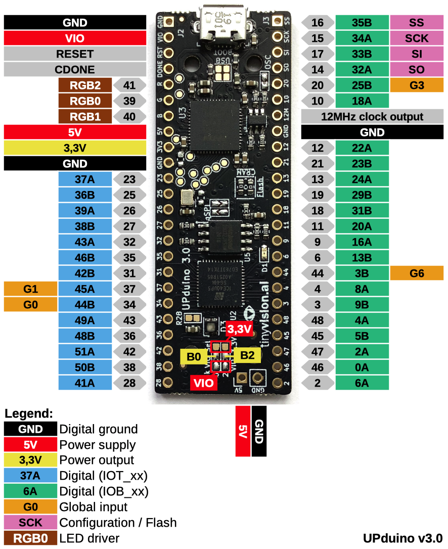
- Today the UPduino will be used solely to power other circuits. Consider the UPduino’s pin:
(Source: reddit post) - If anyone in your group has not used a breadboard before, review and discuss how they work at: Breadboard
How you can use the parts of your kit to power the 74LS00N? Write a brief summary of your plan!
Digital Logic: Real-world Inputs and Outputs
We’ll be using LEDs to observe output values and switches to create inputs. Of course, we will need to ensure both work with the logic levels provided the 7400 series ICs. There are several real-world constraints we need to meet:
- Current to the LED needs to be enough to make it visible
- Current coming out of the ICs need to not exceed what the IC can handle (8mA)
- Inputs should never be “floating” (disconnected from a clear, well-defined voltage)
In order to achieve the first two, we will use a current-limiting 330 Ohm resistor with LEDs: See the SparkFun Overview.
And for the input we will use a 10k Ohm pull-up resistor. SparkFun has an overview of pull-up resistors. We often think of a switch being in the “up” position as being “on”. The DIP switch has an “ON” label that corresponds to the switch being closed (and allowing electricity to flow through it). It may help think about the problem if the DIP switch is installed upside down, making the switch say “NO” (as in not-on) when the switch is down/towards you.
Briefly summarize the concepts of: 1) a current limiting resistor on an output (with an LED) and 2) a “pull-up” resistor to avoid a floating input.
Plan: Testing Inversion
- Identify the parts you need to demonstrate the behavior of inversion using only a NAND gate.
- Plan how you will install and wire parts on your breadboard to utilize power from the UPduino to power the 74LS00N and demonstrate inversion of an input (from a switch).
If you want, you can use a tool like Tinkercad’s circuits support to sketch out most parts of your design: https://www.tinkercad.com/dashboard/designs/circuits (free account required).
Compare & Contrast
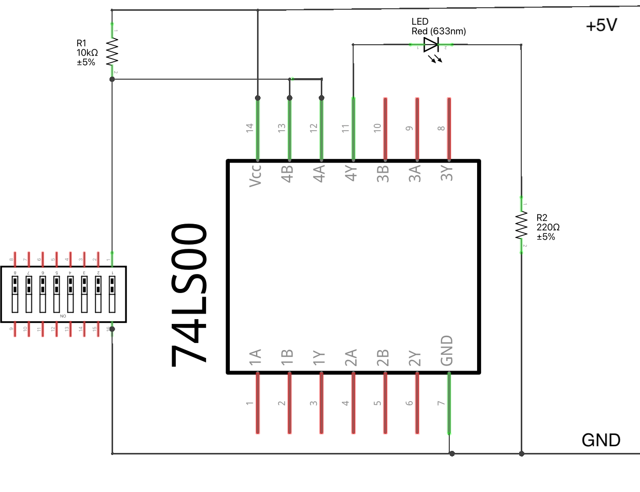
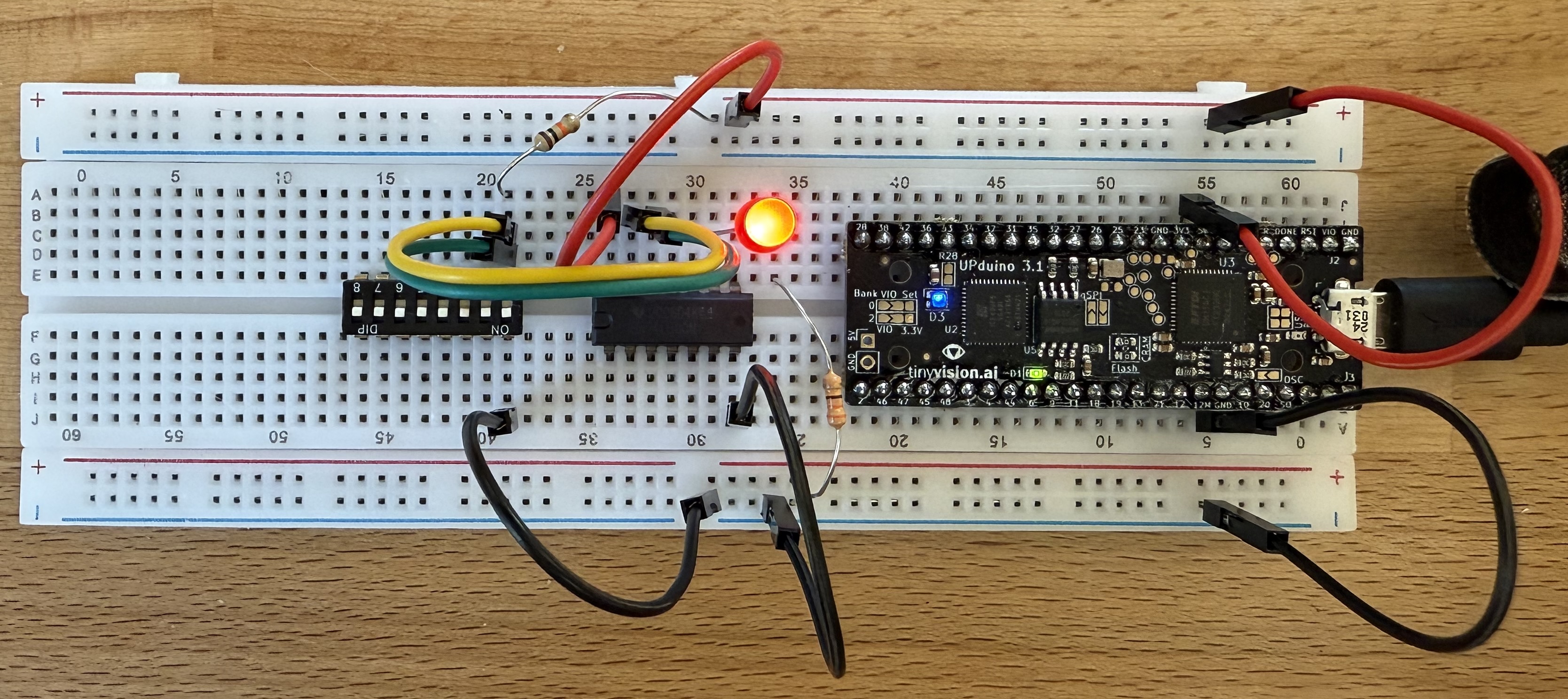
You can expand and reveal one particular approach to demonstrating an inverter below. It includes three views: a “schematic view”, a “breadboard view”, and a picture of an actual breadboard that’s wired up.
A Solution: AFTER designing and diagramming your circuit, click to expand
Schematic View
Here’s a schematic view that omits the power and ground connections to the UPduino:
Breadboard View
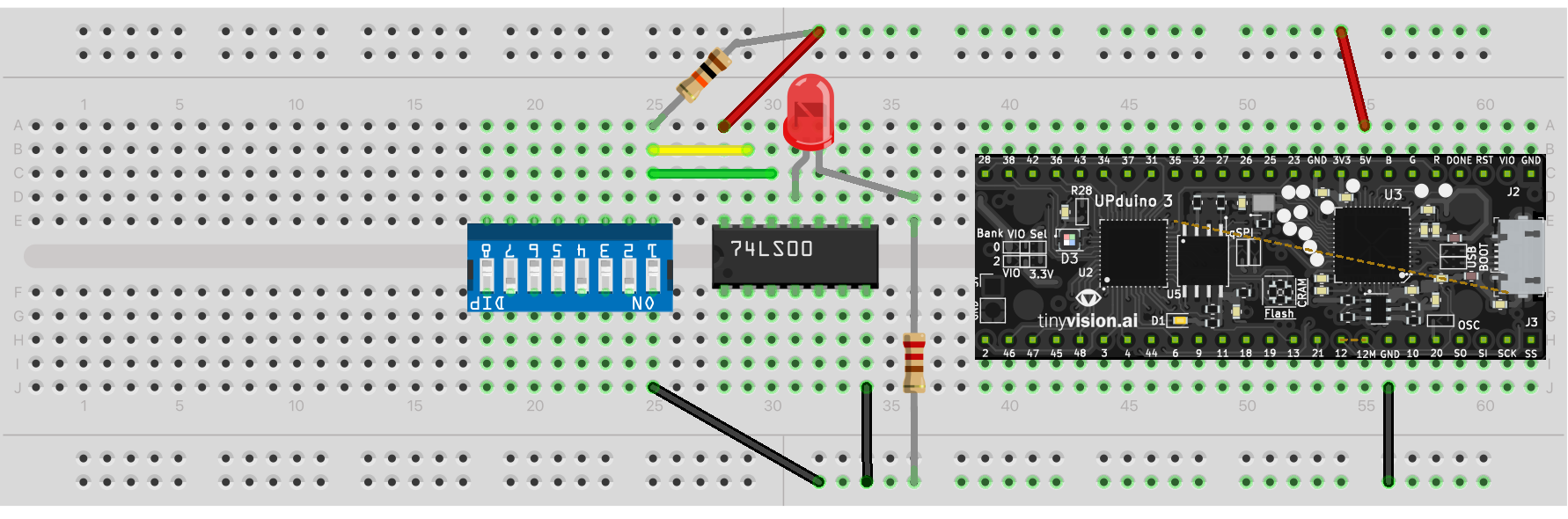
Build View
Here’s an example build:
Compare the above to your plan. Write a justification or explanation for any differences!
Wiring up an Inverter Demo
- Installing and Removing ICs in Breadboards. Install the 74LS00N in your breadboard. You should watch Prof. Steven Bell’s Video (Prof. Bell teaches ES4 at Tufts, which is comparable to 260)
Caution!
Carefully install and remove parts! It’s easy to bend or break the pins (wires) if you aren’t careful. The “pry technique” demonstrated by Prof. Bell to remove parts can also help you avoid hurting yourself — too much pressure on ICs can cause the IC to move quickly and possibly slightly puncture skin.
- Complete all wiring.
-
Have each member in your group review the work.
- Confirm that both the pull-up and current limiting resistors are connected correctly.
- Confirm that ground and 5v are connected correctly to the 74LS00N and the UPduino!
- Have an instructor/TA review your work.
AFTER Confirmation: Test
Once everything has been connected and reviewed, connect power and test it out. Confirm that the value of the switch position is inverted and shown via the LED.
Disconnect Power
When done testing inversion and confirming that you understand the concepts, disconnect the power.
Combinational Logic: Part 1
Using 7400 series logic provided in the kit, demonstrate $Y=AC+BC$.
You’ll need 3 inputs ($A$, $B$, and $C$), so three pull-up resistors.
- Review the parts available and develop a plan for equivalent logic using the available 7400 parts. You may need to come up with an alternate representation of the equation in terms of the available parts. Provide the equation.
- Draw the gate-level schematic in terms of the 7400 series gates you have available.
- Develop the logic table for the behavior.
- Identify how you will wire up the circuit.
- Actually implement it using the breadboard.
- Review your wiring carefully more than once. Confirm that pull-up resistors are used on all inputs, power (5V) and ground are connected correctly to all chips, etc.
- Once you have confirmed the wiring, power it up and test it out. Confirm that the behavior matches the truth table.
- When done, disconnect power!
Combinational Logic: Part 2
Utilize the 74LS151 8-to-1 multiplexer to implement the same logic function ($Y=AC+BC$). As before, plan, wire, double check, power, test, and then disconnect power.
D Flip-Flop
- Use the 74LS175 to test the behavior of a flip-flop.
- Use a dip switch to control a $D$ input
- Use another dip switch to control the clock ($CLK$) input
- Use yet another dip switch to control the reset ($\overline{CLR}$). The bar indicates that it’s “active low”.
- Draw a schematic of the circuit and label the pins used for the chip.
- Double check your work
- Power it up
- Test 1
- Ensure the $\overline{CLR}$ is high (5V)
- With the D input low, clock the circuit.
- Now move the D input high, what happens to the output?
- Clock the circuit with the D input high.
- Explain what causes the output to change.
- Test 2:
- With the input high, lower the switch connected to $\overline{CLR}$, cycle the clock in this configuration. Explain the output of the flip-flop
- Set the $\overline{CLR}$ high. What happens to the output? Now cycle the clock.
- Briefly explain the purpose of the $CLK$ and the $\overline{CLR}$
- What is the benefit of having both the output of the flip-flop and the inverse of the output available on the chip pins?
State Machine
Construct a real, working version of the state machine given as an extra class example: Prof. Feher’s State Machine Example (PDF) (or Prof. Feher’s State Machine Example (docx) )
Submission / End-of-class
Discuss your work/findings with TAs/instructors. Submit a copy of the questions with everyone’s name at the top (at least one person should submit it, but it’s ok if everyone does).
Submission Link: Canvas