Studio 7B
Overview / Reminder
- Studios are a time to explore the material and refine your understanding.
- You should NOT “divide and conquer” to complete all of the studio. The time is meant for improving your understanding.
- You should ensure that everyone in your group contributes to and benefits from the work.
Artifacts for this studio
Complete the code and add answers to questions in the “questions.md” file in the repository.
Studio Setup
The repo link Studio 7B
Data Path and Fetch, Decode, Execute Cycle
Consider the simple, single-cycle RISC-V CPU model:
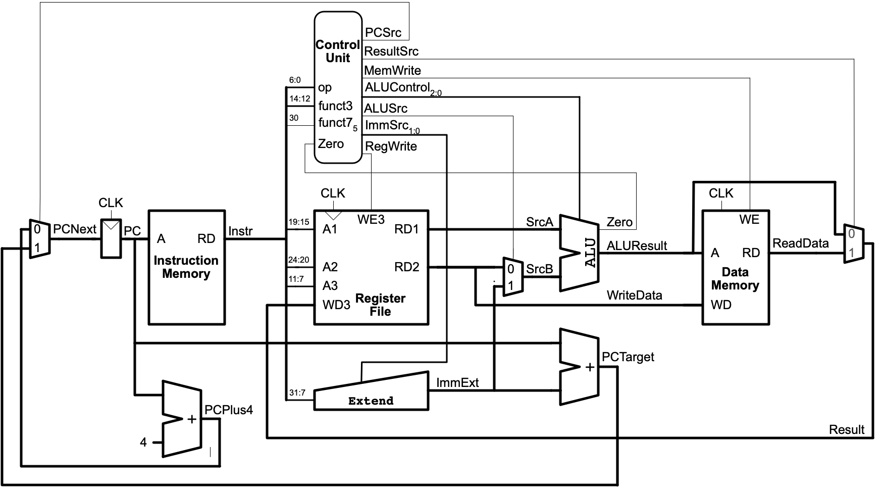
Control Signals
As covered in class, instructions are “decoded” but simple, combinational logic. The “decoding” just controls parts of the CPU to ensure it performs the designated operation, on the desired data, with the outcome that’s expected for the architecture.
BEQ: Part 1
Signals
Assuming that t0 is 0, PC is 100, and loop resolves to -8. Describe both: (a) the control signals (all the outputs of the the combination logic from the “Control Unit”) and (b) the outputs of the ALU (note the ALU has two outputs) for:
beq t0,zero,loop
Behavior
Provide a brief description of how each of the following parts of the CPU is involved in the execution of this instruction and how they may be updated at the end of the clock cycle:
- PC Register
- Instruction Memory
- Register File
- ALU
- Any of the other adders or units involved
BEQ: Part 2
What signals (control and from ALU) would change if t0 is 1 instead?
Starting with 7 Segments and Switches
Caution!
The UPduino should not be plugged in to your computer!
Seven-Segment Displays have long been used in digital logic. As the name suggests, they have “seven segments”, each of which can be “shown” or “not”. Typically a segment is an LED or LCD cell. Enabling and disabling segments can be used to display numbers and even some letters. The segments are typically shaped to facilitate thie and are given letters to help identify each one.
(By Uln2003 - Own work, CC0, https://commons.wikimedia.org/w/index.php?curid=69807877)
Your kits contain an LED & Key module that includes 8, 7-segment displays, 8 traditional LEDs, and 8 push buttons. The module is controlled by the TM1638, which can be controlled by a state machine!
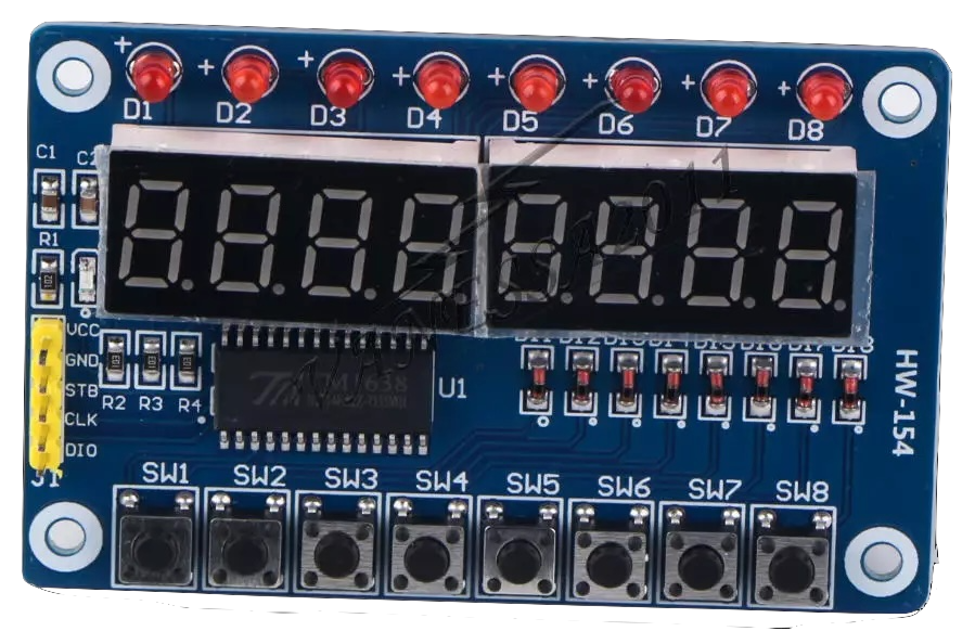
Your kit also comes with a male to female jumper wiires that can connect your breadboard to the module. Tear off a group of 5 wires (no need to separate them into indivudal strands — it’ll be a little easier if they are connected together):

Use the cable to connect the UPduino to the board:
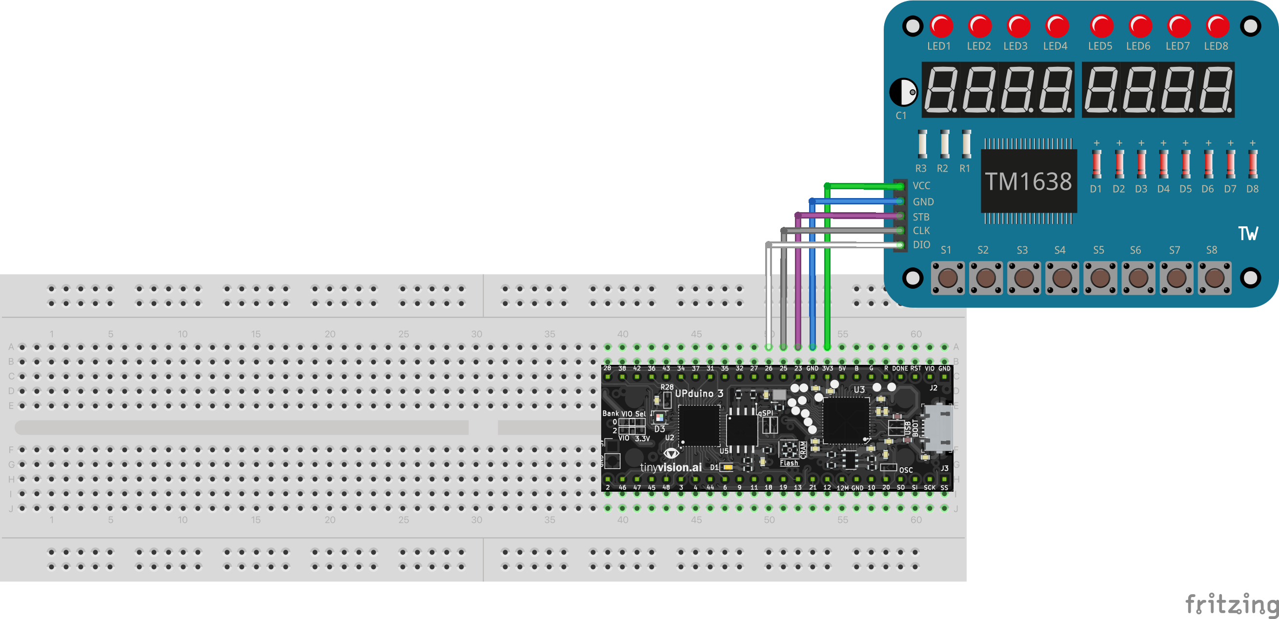
| UPduino Pin Number/Name | Board Pin Name |
|---|---|
| 3V3 | VCC |
| GND | GND |
| 23 | STB |
| 25 | CLK |
| 26 | DIO |
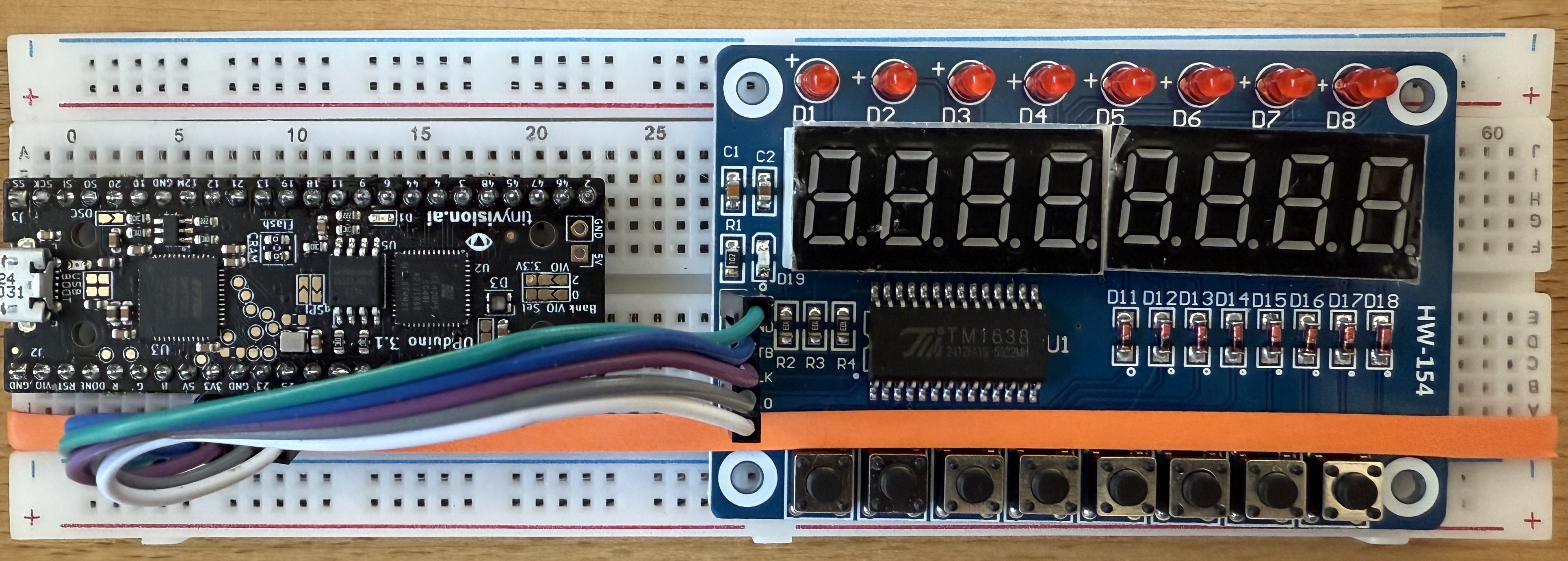
It should look about like below (the board has been rotated and a rubber band has been used to hold it to the breadboard):
Testing
- Double check all wires.
- Connect the UPduino to your computer with the USB cable.
- Start the
FPGA Programmer Servertask. - Connect the the UPduino. (Review the FPGA Programming page if needed)
- Today’s Codespace contains a
ledandkey_test.binimage. Program it on the UPduino. If it works, the board should show the digits 7-0 and pressing each button should cause a corresponding LED to light up. Confirm that the board is connected correctly and works.
Segments and Combinational Logic
Your repository contains a combinational_segments project with corresponding tasks. Complete the TODO items in it to begin practicing use of the display and keys.
Sequences and Segments
Your repository contains a soda project that has a det.sv module:
module det(
    input clock,
    input logic in,
    output logic out
);
    logic o;
    always_ff @(posedge clock)
        o <= in;

    assign out = in & ~o;
endmodule
Consider the following signals:

Assume that clock is always being used for the clock and has a total period of 20 units of time.
Test Cases
Describe behavior of out in response to each of the examples possibly being used as the input (in). I.e., what would out do in response to clock and the input provide by example one? And if the input is from two?, Etc,
Summarize
This module can be really useful when working with buttons. Buttons rely on human reaction time, which is often much much slower than an FPGA’s clock. Explain what this module does and how it may be useful when working with buttons.
States and Segments
If you are working with others, compare/contrast your solutions to Homework #5’s “Soda Machine”.
The soda project includes soda.sv that needs the actual Soda machine state code added. It has three new ports: display0, display1, and anykey. As you can see in top.sv, the diaplay ports are just connected to the right two digits of the display. They should be used to display the total change added to the machine so far. anykey indicates that one of the coin keys (nickel, dime, quarter) is still held down. You should stay in any “dispense” state while the key is still pressed.
Review the top.sv file. Part of top is pre-configured for you, but some work remains. Each key is connected to one of the right-most LEDs so you can confirm when a key is pressed, but they still need to be connected to the soda module. You should use three instances of the det module to connect buttons to your soda module.
Each of the outputs of the soda module is already connected to an LED on the right side of the board, which can help you see when the soda machine is dispensing or returning change.
Why Det?
Use of the det module, which is a state machine itself, can simplify the soda state machine. Questions:
- What would happen if the
detmodule isn’t used at all (keys are connected directly to state machine inputs)? - How could the state machine be modified to avoid that behavior?
- Compare/contrast the use of the
detmodules vs. the alternative.
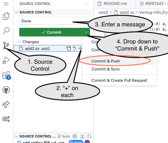
Commit and Push Work
When done, you need to “Commit and Push” work to share it back to the GitHub repository from the Codespace.
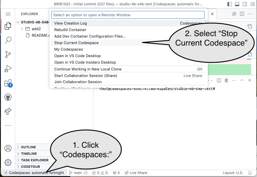
End of Studio: Stop the Codespace
Caution!
Be sure to “stop” your Codespace. You have approximately 60 hours of Codespace time per month. Codespaces often run for ~15 minutes extra if tabs are just closed.
Submission / End-of-class
Discuss your work/findings with TAs/instructors.
