Studio 7A
Overview / Reminder
- Studios are a time to explore the material and refine your understanding.
- You should NOT “divide and conquer” to complete all of the studio. The time is meant for improving your understanding.
- You should ensure that everyone in your group contributes to and benefits from the work.
Artifacts for this studio
Complete the code and add answers to questions in the “questions.md” file in the repository.
Studio Setup
The repo link Studio 7A
Hardware Setup
Setup and testing
Go through the setup described in FPGA Programming.
Trouble Shooting
Review the Trouble Shooting section of FPGA Programming. Explain things you should check if the FPGA isn’t behaving as you expect. (Answer the question in questions.md)
Controlling LEDs
Common Anodes
The UPduino has an RGB LED, which is three lights (red, green, blue) in a single small package. Combining them has two benefits: colors can appear to be “mixed” because they are so close together and a wire can be shared among the LEDs. The RGB LED on the UPduino is a common anode: the connection that needs to be at a higher voltage to light the LEDs is shared and the grounds of each are individual.
Review DigiKey’s Common Anode vs. Common Cathode description. Based on this, what logic value would be necessary to turn on a LEDs. (Answer the question in questions.md)
Active High vs. Active Low
Do a quick search for “active low” in regards to digital logic. Summarize in your own words what is meant by “active low” and “active high”. (Answer the question in questions.md)
Verilog
Review the code in led/led.sv, which is configured to allow Verilog combinational logic to control the RGB LED.
- Activate both red and green to make the LED light yellowish. Use the
led: imagetask to create a bit stream and then program it to the FPGA. - After that, it may be easier to work with logic where a
1is on and0is off. Add more logic that will define three new signals,red,green, andbluethat will light the corresponding LED when a1. - Finally, mix red and blue using these new signals to get a purplish hue.
Inputs: Switches
Our kit includes DIP switches. Like many simple switches, DIP switches will either connect an input to a defined voltage or leave it disconnected (and possibly “floating”). The iCE40 FPGA is able to include “weak pull ups” on it’s inputs. If the input is truly floating, it will be pulled “up” (to a logic 1).
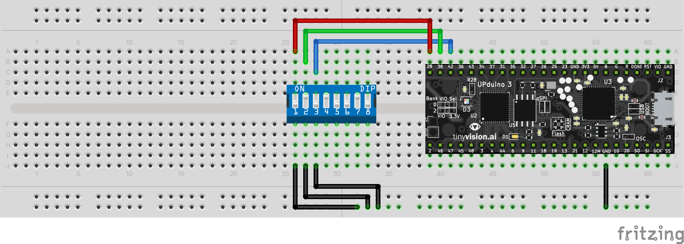
Connect the DIP switches as shown in this diagram:

DIP Switch Logic
Review the diagram. When the switch is “down” (off) there is no connection between the top and the bottom of the IC. That is, the top pin. What does this mean for the logic levels? What will be the logic value on the UPduino when the switch is “on” and when it is “off”? (Answer the question in questions.md)
Switching LEDs
Complete the code in switches/switches.sv so the three switches control the three LEDs (using the switches: image task):
- The DIP switch should be oriented and connected as shown
- When switch 1 is in the ON position,
redshould be on (and, of course, red should be off when the switch is not on) - When switch 2 is in the ON position,
greenshould be on (and, of course, red should be off when the switch is not on) - When switch 3 is in the ON position,
blueshould be on (and, of course, red should be off when the switch is not on)
Combinational Logic: Full adder
Complete the logic needed in fulladder/fulladder.sv for a full adder.
FPGA designs often have a “top” module that defines the connections coming in to the FPGA. top.sv is the top module. Declare an instance of a fulladder in it where designated. Connect the switches and LEDs to your full adders inputs and outputs, then test your work. (Note that the top module already defines “active high” signals for the three leds and the three switches)
Review the blink/top.sv module and the blink/blink.sv module. Complete blink.sv as described such that it will blink the red LED on for half a second every second.
Then update top module to control a second LED, like the blue LED. Use parameters to have it activate when the LED is off. (I.e., on for half a second, but not starting until the red is off). (Use the blink: image task)
Try variations.
Challenge: Pulse Width Modulation
You may note that the LED are very very bright. A common way to dim LEDs is to have them on for a smaller fraction of time via a technique called Pulse Width Modulation (PWM). You can use the low bits of your counter, like the last 12 bits, to do a variant of PWM. For example, if those last 12 bits are less than 10, the LED could be on and when they are greater than 10 it could be off. This would only have the LED on for $\frac{10}{2^{12}}$ of the time and dim it.
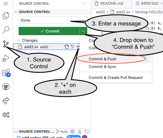
Commit and Push Work
When done, you need to “Commit and Push” work to share it back to the GitHub repository from the Codespace.

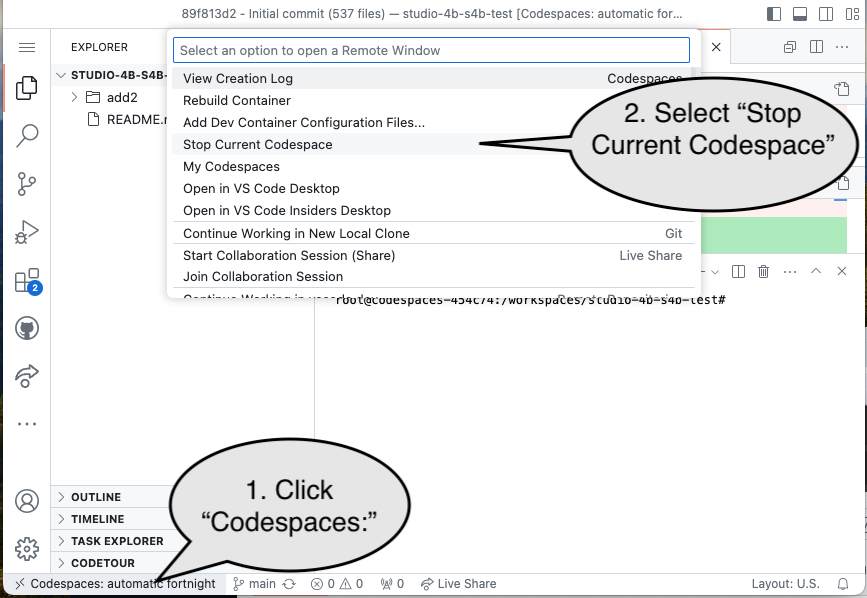
End of Studio: Stop the Codespace
Caution!
Be sure to “stop” your Codespace. You have approximately 60 hours of Codespace time per month. Codespaces often run for ~15 minutes extra if tabs are just closed.

Submission / End-of-class
Discuss your work/findings with TAs/instructors.
