Studio 3B
Overview / Reminder
- Work in small groups
- Studios are a time to explore the material and refine your understanding.
- You should NOT “divide and conquer” to complete all of the studio. The time is meant for improving your understanding.
- You should ensure that everyone in your group contributes to and benefits from the work.
Artifacts for this studio
Include an answer to questions in the numbered sections in your submission. Include the relevant section number for each answer, like 1.1.
Chapter 3: Synchronous Logic
State Representations
Binary Counting vs. One Hot Encoding
Two of the extremes in state encoding are binary encoding (counting states from 0 to $n$) and the one-hot encoding. Consider a Moore-style machine with 10 states, a single input named input, and a single output named output:
- How many bits, $k$, are needed for a binary state encoding?
- Assume that the
output’s value depends on being one of three specific states, either state 0, state 6, or state 9. A pseudo-code form ofoutput = in_state_0 + in_state_6 + in_state_9. Provide the complete equation for the output in terms of the state bits, $Q_k \cdots Q_0$. - How many bits, $l$, are needed for a one-hot state encoding?
- Provide the complete equation for the
outputin terms of the state bits, $Q_l \cdots Q_0$.
Stating the Abstract
Assume you have more generic problem with $n$ states and that the output or next state equations will depend on being able to identify or detect each of the $n$ states somehow (that is, you’ll need some circuit to determine if you’re in state 0, and another to determine if you’re in state 1, etc. This is very comparable to the equations you created in the prior part).
Based on how both flip-flops are constructed and how states are detected:
- Come up with formulas that describe the minimum number of
ANDandORgates needed (i.e. the number needed just for flip-flops and state detection) for each encoding. You may assume that multi-input (more than binary)ANDgates are being used.- For binary encoding
- For one-hot encoding
- Total space taken to construct circuits will be based on the number of wires used and the width of
ANDandORgates being used. Try to estimate how the space needed to construct the circuits will differ. For example, you may start with the assumption that a $j$-inputANDtakes $\frac{j}{2}$ times more space than a 2-inputANDand that $k$ wires take a little more than $k$ times the space of a single wire. - Based on the prior work, provide rough guidance for when someone wants to minimize space for:
- When one may prefer binary encoding.
- When binary and one-hot encoding may be nearly identical.
- When one may prefer one-hot encoding.
Flip-Flop Timing: Empirical Measurements
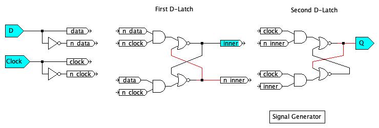
In class we constructed an SR Latch from cross-coupled NOR gates. Then stacked some AND gates in front of the SR Latch to make the D-Latch. We then used two D Latches in sequence to create a D Flip-Flop, which has much more precise control of when data is captured. The D two D Latches use opposite phases of the clock: The first D-Latch is transparent when the clock is low and captures the data value when the clock level is high. The second D-Latch is the opposite: it is transparent when the clock is high and captures the value when the clock is low.
Construct the following D-Flip-Flop Model in JLS:
Test Your Flop Flop
- Ignoring the loops in the circuit, what is the propagation delay from
DtoQ? Round up to the nearest 100 and consider that to be a safe value for the clock cycle. - Test your work. Confirm that you can store both a
1and a0.
Describe any unusual behavior at the start of the simulation.
There are multiple facets of timing that are important in synchronous circuits, including the maximum clock speed and ensuring that D Flip Flops behave stably.
Estimating Parameters
Using the JLS model’s timing, find:
- $t_{dq}$: The propagation delay from a change in
Duntil a change inQ. - $t_{cq}$: The propagation delay from a change in
Clockuntil a change inQ
Empirically Finding Setup Times & Influences
It may help to sketch out timing signals on a graph for the following problems
A flip-flop’s setup time ($t_{setup}$) is the amount of time the D value must be stable before a clock cycle to reliably store a value. Construct a set of signals that:
- Initializes the flip-flop to a known value (maybe the first $t$ units of simulation time is initialization)
- Have
Dchange in close proximity to the clock going high. Determine the setup time (timeDneeds to be in a given value) before the clock goes high to reliably captureD’s value. Confirm that the correct value is being stored correctly! - Check your work if
Dis going to the opposite values. For example, if the prior test was changing the value stored from a0to a1, repeat the test to see if you get the same result when going from a1to a0. - Try to identify which circuit elements primarily dictate this setup time. Reason about the behavior of the circuit.
- Test your reasoning/guessing buy: a) Right-click on the element(s) you think dictate the setup time and select
Change Timing. Change the time(s) to unique values not used by other elements. Then: b) Test your hypothesis to confirm that the D Flip-Flop works and fails relative toDbeing set based on the new timing relative to the clock.
Explain your results.
Resetting Timing
Reset all timing to base values. You can use the Global menu in JLS and select Reset all propagation delays.
Empirically Finding HOLD Times & Influences
A flip-flop’s hold time ($t_{hold}$) is the amount of time the D value must be stable after a clock cycle to reliably store a value. Do a variation on the prior part to determine what influences a D Flip Flop’s Hold time.
Aperture Time
The aperture time is the total amount of time the D value must be stable. What is the default aperture time for this flip-flop in JLS?
Warning
JLS simulates perfect conditions of ideal logic. It provides a useful model for understanding some of the factors in circuit timing, but
Submission / End-of-class
Discuss your work/findings with TAs/instructors. Submit a copy of the questions with everyone’s name at the top (at least one person should submit it, but it’s ok if everyone does).
Submission Link: Canvas